Introduction to Globe valves
Globe valves
A Globe valves is a linear motion valve and are primarily designed to stop, start and regulate flow. The disk of a Globe valve can be totally removed from the flowpath or it can completely close the flowpath.
Conventional Globe valves may be used for isolation and throttling services. Although these valves exhibit slightly higher pressure drops than straight=through valves (e.g., gate, plug, ball, etc.), they may be used where the pressure drop through the valve is not a controlling factor.
Because the entire system pressure exerted on the disc is transferred to the valve stem, the practical size limit for these valves is NPS 12 (DN 300). Globe valves larger than NPS 12 (DN 300) are an exception rather than the rule. Larger valves would require that enormous forces be exerted on the stem to open or close the valve under pressure. Globe valves in sizes up to NPS 48 (DN 1200) have been manufactured and used.
Globe valves are extensively employed to control flow. The range of flow control, pressure drop, and duty must be considered in the design of the valve to avert premature failure and to assure satisfactory service. Valves subjected to high-differential pressure-throttling service require specially designed valve trim.
Generally the maximum differential pressure across the valve disc should not exceed 20 percent of the maximum upstream pressure or 200 psi (1380 kPa), whichever is less. Valves with special trim may be designed for applications exceeding these differential pressure limits.
Body designs of Globe valves
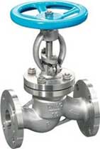
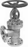
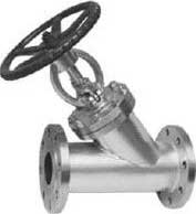
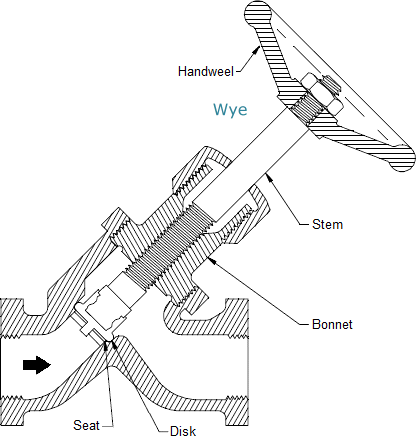
There are three primary body designs for Globe valves, namely: Tee Pattern or Z-body, Angle Pattern and Wye Pattern or Y-body body.
TEE PATTERN GLOBE VALVE DESIGN is the most common body type, with a Z-shaped diaphragm. The horizontal setting of the seat allows the stem and disk to travel perpendicular to the horizontal line. This design has the lowest coefficient of flow and higher pressure drop. They are used in severe throttling services, such as in bypass lines around a control valve. Tee-pattern Globe valves may also be used in applications where pressure drop is not a concern and throttling is required.
ANGLE PATTERN GLOBE VALVES DESIGN is a modification of the basic Tee Pattern Globe valve. The ends of this Globe valve are at an angle of 90 degrees, and fluid flow occurs with a single 90 degrees turn. They have a slightly lower coefficient of flow than wye-pattern Globe valves. They are used in applications that have periods of pulsating flow because of their capability to handle the slugging effect of this type of flow.
WYE PATTERN GLOBE VALVES DESIGN, is an alternative for the high pressure drop, inherent in Globe valves. Seat and stem are angled at approximately 45 degrees, what gives a straighter flowpath at full opening and offer the least resistance to flow. They can be cracked open for long periods without severe erosion. They are extensively used for throttling during seasonal or startup operations. They can be rod through to remove debris when used in drain lines that are normally closed.
Disk and Seat and Stem of Globe valves
DISK: The most common disk designs for Globe valves are: ball disk, composition disk and the plug disk. Ball disk design is used primarily in low pressure and low temperature systems. It is capable of throttling flow, but in principle it is applied to stop and start flow.
Composition disk design uses a hard, non-metallic insert ring on the disk, which ensures a tighter closure.
Plug disk design provides better throttling than ball or composition designs. They are available in many different designs and they are all long and tapered.
SEAT: Globe valve seats are either integrated or screwed in to the valve body. Many Globe valves have backseats inside the Bonnet. Back seats provides a seal between the stem and Bonnet and prevents system pressure from building against the valve pakking, when the valve is fully open. Back seats are often applied in Globe valves.
STEM: Globe valves uses two methods for connecting the disk and the stem: the T-slot and the disk nut construction. In the T-slot design, the disk slides over the stem, while in the disk nut design, the disk is screwed into the stem.
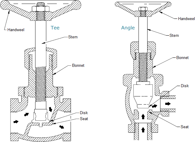
Construction of a Globe valve
Globe valves usually have rising stems, and the larger sizes are of the outside screw-and-yoke construction. Components of the Globe valve are similar to those of the gate valve. This type of valve has seats in a plane parallel or inclined to the line of flow.
Maintenance of Globe valves is relatively easy, as the discs and seats are readily refurbished or replaced. This makes Globe valves particularly suitable for services which require frequent valve maintenance. Where valves are operated manually, the shorter disc travel offers advantages in saving operator time, especially if the valves are adjusted frequently.
The principal variation in Globe-valve design is in the types of discs employed. Plug-type discs have a long, tapered configuration with a wide bearing surface. This type of seat provides maximum resistance to the erosive action of the fluid stream. In the composition disc, the disc has a flat face that is pressed against the seat opening like a cap. This type of seat arrangement is not as suitable for high differential pressure throttling.
In cast-iron Globe valves, disc and seat rings are usually made of bronze. In steel-Globe valves for temperature up to 750°F (399°C), the trim is generally made of stainless steel and so provides resistance to seizing and galling. The mating faces are normally heat-treated to obtain differential hardness values. Other trim materials, including cobalt-based alloys, are also used.
The seating surface is ground to ensure full-bearing surface contact when the valve is closed. For lower pressure classes, alignment is maintained by a long disc locknut. For higher pressures, disc guides are cast into the valve body. The disc turns freely on the stem to prevent galling of the disc face and seat ring. The stem bears against a hardened thrust plate, eliminating galling of the stem and disc at the point of contact.
Flow direction of Globe valves
For applications with low temperature, Globe valves are normally installed so that the pressure is under the disc. This contributes an easy operation and helps protect the packing.
For applications with high temperature steam service, Globe valves are installed so that the pressure is above the disk. Otherwise, the stem will contract upon cooling and tend to lift the disk off the seat.
Advantages and Disadvantages of Globe valves
ADVANTAGES:
- Good shutoff capability
- Moderate to good throttling capability
- Shorter stroke (compared to a gate valve)
- Available in tee, wye, and angle patterns, each offering unique capabilities
- Easy to machine or resurface the seats
- With disc not attached to the stem, valve can be used as a stop-check valve
DISADVANTAGES:
- Higher pressure drop (compared to a gate valve)
- Requires greater force or a larger actuator to seat the valve (with pressure under the seat)
- Throttling flow under the seat and shutoff flow over the seat
Typical Applications of Globe valves
The following are some of the typical applications of Globe valves:
- Cooling water systems where flow needs to be regulated
- Fuel oil system where flow is regulated and leaktightness is of importance
- High-point vents and low-point drains when leaktightness and safety are major considerations
- Feedwater, chemical feed, condenser air extraction, and extraction drain systems
- Boiler vents and drains, main steam vents and drains, and heater drains
- Turbine seals and drains
- Turbine lube oil system and others


Reviews
There are no reviews yet.